What is the mechanical interface tool and how can it be used to improve part positioning?
The Mechanical Interface tool in CATIA, introduced in version 2018x, allows users to define interfaces directly within parts during the design phase. These interfaces specify how parts will connect or interact in assemblies, such as bolt holes, grooves for O-rings, or mating faces. Traditional constraints (e.g., coincidence, contact) can break when parts are updated or moved between assemblies. The mechanical interface tool avoids this issue by embedding positioning logic directly into the part design. This ensures robust and reusable connections that adapt to changes without requiring manual rework. This approach simplifies assembly processes by predefining connection points and relationships.
To use the mechanical interface tool:
- Use the part design workbench to create geometry.
- Specify mechanical interfaces (e.g., holes, grooves) using the mechanical interface tool.
- In the assembly design workbench, insert parts into an assembly.
- The predefined interfaces allow quick and accurate positioning without additional constraints.
- If a part’s geometry changes, update its interface definition directly in the part file. This change propagates automatically across all assemblies using that part.
Most frequently asked questions
Looking for answers?
In the TECHNIA knowledge base you’ll find the answers to your questions. Search our database of 200,000+ articles written by experienced TECHNIA experts.
- Visit the TECHNIA Customer Care portal via this link: https://technia.jira.com/servicedesk/customer/portal/11
- This link will lead to ‘sign up’ page when you are logging in for the first time
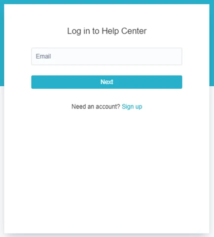
- Click on ‘sign up’ to create your account
- Fill in the email address and send the link
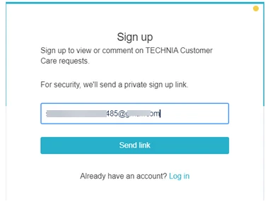
-
A confirmation link will be sent via email
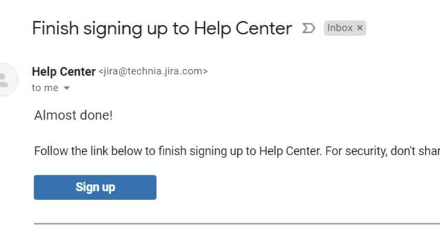
- Click on the ‘sign up’ link in email and set your account name and password
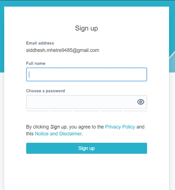
- You can now access the portal
Please check in the web portal https://technia.jira.com/servicedesk/customer/portal/11 if you may have accidentally disabled email notifications for your TCC ticket.
If it looks like this, it is ok and you should receive notifications:

If it looks like that, you need to turn the notifications back on:

As 3DEXPERIENCE moves to the latest version, there will be changes in the Java Runtime versions required by the platform.
Why Upgrade Java?
Java is a continually evolving software, with new versions being released regularly. These updates typically include bug fixes, security patches, and functional improvements. For IT departments, staying up-to-date with the latest versions of Java helps minimize security vulnerabilities and ensures that systems are protected against the latest threats.
However, as much as you might be inclined to upgrade to the latest version, it’s crucial to remember that 3DEXPERIENCE is designed to work with specific versions of Java that have been tested and validated by Dassault Systèmes.
What Java versions are supported for 3DEXPERIENCE R2025x?
As 3DEXPERIENCE moves to R2025x, there will be changes in the Java Runtime versions required by the platform. Here are the updates:
- IBM Semeru Runtime Open Edition for Java 21.0.4 (JDK) will be the new validated platform.
- IBM Semeru Runtime Open Edition for Java 21.0.x (JDK) with x > 4 will be a compatible platform.
- Oracle JDK 21.0.x with x ≥ 4 will also be a compatible platform.
It’s important to adhere strictly to these versions, as using any other version, even if it appears to work, could cause compatibility issues or prevent you from receiving support from Dassault.
How to Update Java for 3DEXPERIENCE?
Upgrading Java for your 3DEXPERIENCE platform is a straightforward process, but it’s important to follow the proper steps to avoid any disruptions.
Step 1: How do I check which Java version I am currently using?
Before you upgrade, it’s essential to know which version of Java you are currently using. This will help ensure you’re updating to the correct version. To check your Java version, you can run the following command in your command line or terminal:
java-version
This will display the version of Java currently installed on your system.

Step 2: Uninstall the old Java version
If your current Java version is no longer supported, you’ll need to uninstall the old version. Go to your Control Panel (Windows) or System Preferences (Mac), locate the old Java version, and uninstall it.

Step 3: Download and install the new Java version
Next, download the required Java version from a trusted source. You can get the IBM Semeru Runtime Open Edition or Oracle JDK from their respective websites.

Step 4: Initiate installation
Start the .msi file that has been downloaded in the previous step to initiate the installation. Click Next.

Step 5: Terms and conditions
Accept terms and conditions and click Next.

Step 6: Set registry keys
Use the drop-down arrows and set Java Home variable and Javasoft (Oracle) registry keys as “Will be installed on local hard drive.” Once done, click next.


Step 7: Complete installation
Click on Install and wait for the installation to be completed. Once done, click Finish to close the installation window.

Step 8: Restart 3DEXPERIENCE services
Once the new Java version is installed and verified, restart your 3DEXPERIENCE services to ensure the platform is using the updated Java version.
What if I install Java in a different directory?
During installation, ensure that Java is installed in the same directory as your previous Java version. For instance, if your previous installation was in D:\Java, install the new version in the same directory. If the installation path changes, 3DEXPERIENCE may not be able to locate Java, which could prevent the platform’s services from starting correctly.
How do I check which Java version I am currently using?
After installation, verify that the correct version is now in place. Use the java-version command to confirm the version change.
How to raise a TECHNIA Customer Care Support request
VIA Portal:
https://technia.jira.com/servicedesk/customer/portals


VIA EMAIL:
support@technia.com

TECHNIA CONFIDENTIAL
To determine the FlexNet hostid please run cmd.exe as administrator:

Inside the Command Prompt window please type the command ipconfig /all
Example:

Please send the complete output of the command to your contact at TECHNIA.
TECHNIA CONFIDENTIAL
This short guide lists the steps to enrolling a DSLS nodelock license.
Please copy the licences received onto the computer.
Note: Do not place in C:\ProgramData\DassaultSystemes\License
1. Create Licenses Folder in C:\ProgramData\DassaultSystemes (if this doesn’t already exist).
Note: If current licences already exists in the Licences folder, please delete these now.
2. Start > Programs > CATIA > Tools > Nodelock Key management V5-6R20XX
3. Click File > Import

4. Select the license (placed on the desktop) then click Open

The enrolled license will show up in the list after.
TECHNIA CONFIDENTIAL
Please note the supported operating systems according to the information in the Program Directories:
https://media.3ds.com/support/progdir/all/?pdir=3Dexp
Starting with DSLS R2025x FD03 the standalone DS License Server is supported in Hyper-V on Windows Server.
Network card teaming is not supported.
Further information can also be found in the following Knowledgebase article: Supported hardware systems for DSLS License Server
Please download DSLicTarget.exe
After the download, the file DSLicTarget.exe is located in your Downloads folder.
Please open Windows Explorer and take a look at your Downloads folder.

In Windows Explorer, click into the address line at the top, enter “cmd” (without quotation marks), and press Enter/row change.

A command prompt (cmd.exe) window appears.
Type the command “DSLicTarget –t”:

Select the menu “Edit\Mark”:

Mark the output of the command “DSLicTarget –t” with the left mouse button:

Copy the marked text with the key to the Windows clipboard.
Now you can insert the copied text from the Windows clipboard into your email application and send it to your contact at TECHNIA.
This guide will explain how to configure a client machine to request and use a (concurrent or floating) license from a DSLS license server.
- Ensure a Dassault Systèmes product is installed (e.g. CATIA V5)
- Using a ‘Windows File Explorer’, browse to the folder: –
C:\ProgramData\DassaultSystemes\Licenses
Note: The folder ‘ProgramData’ is normally a hidden folder. You can type that piece into the address bar OR un-hide the folder.
Note: If the ‘Licenses’ folder does not exist, browse to C:\ProgramData\DassaultSystemes and create a ‘New Folder’ called ‘Licenses’ as shown below:


Inside the Licenses folder, open the DSLicSrv.txt file.
Note: If the ‘DSLicSrv.txt’ text file does not exist, create a ‘Text Document’ called ‘DSLicSrv’ as shown in the pictures below: –
Caution: Ensure you do not finish up with a doubled-up file extension. The file MUST be called DSLicSrv.txt and NOT DSLicSrv.txt.txt It is suggested you have ‘Hide extensions for known file types’ deactivated in Folder Options to spot this error.


In the text file ‘DSLicSrv.txt’, enter the required information in the following format: :
Note: The ServerName should be entered exactly as it is named.
The licensing port number by default is 4085, so please use 4085 (Unless this was changed during DSLS installation). e.g. If the License server is called ‘server1’ the text file should have a line server1:4085 .
Also note: If the DSLS license server is the same PC as the license client i.e. server and client on the same PC, you may use the name localhost e.g. localhost:4085

Save the text file and proceed to open your DS Application. Do not forget, the first time you start the application, it will ask you to select a license.
Note: If there is an additional server, e.g. server2, simply enter it in the next line.

Troubleshooting
Cannot get a license from the license server? Check the following:
- Is Window’s firewall off on both the client and server?
Action: Temporarily disable the firewall on the server and the client. If it starts working, port 4084 and/or 4085 are being blocked. - Can you ping the server (using the name you entered)?
Action: Potential misspelling of server name or network problem. - Have you got the latest DSLS?
Action: The DSLS version installed should at least equal the version of the Dassault application you are using. - Is the spelling of the server name and/or port number correct?
Action: Correct any misspelling of server name or port number. - Is the path to the DSLicSrv.txt (and indeed the name of the DSLicSrv.txt file) spelt correctly?
Action: Correct any misspelling of the folder name(s) or the DSLicSrv configuration filename. - Is the license server configured correctly, with the licenses installed and the license service running?
Action: Configure the DSLS license server correctly.
TECHNIA CONFIDENTIAL
If you have not yet installed Dassault Systèmes License Server (DSLS), please read the following KB article first:
This guide will explain how to configure the Dassault Systèmes License Server (DSLS) and enroll DSLS licenses using the License Administration Tool provided by Dassault Systèmes.
Please save the .LICZ attachment from the licensing E-mail you received, into an easy to find folder on the license server.
1. Once the DSLS licensing app is installed on the server, go to ‘Start > Programs > DS License Server > License Server Administration’ to run the admin tool on the server.

2. To create a new server click the Servers‘ tab and click ‘New‘

3. Enter localhost‘ as the server name and click ‘Ok‘ to continue (if you chose a different port earlier, change the port to match)

4. Select your server from the list and click the Connect function from the ‘Servers’ menu at the top OR ‘Right mouse button’ on the server in the list and select ‘Connect’.

Note: The server will become bold when connected as shown below.

Note: However, if no licenses have been installed yet (and the server is not activated), there will be a red cross on the ‘Server status’ icon as shown below.

5. Now you can enroll your license key(s) by clicking the License‘ tab and then ‘Enroll‘

6. Locate the license key (licz) and select Open

7. The license(s) contained in the licence file will be enrolled and a message like the one below will appear. Click ‘OK’

The above indicates successful license enrollment, and the system is ready to use. You may now close the License Administration Tool. The license file you have (xxxxx.LICZ) may be discarded.
Note: If you get an error message, the primary reason is probably that you are trying to enroll the license(s) on a server where the DSLS Target ID does NOT match the target ID that the license file was created for.
To configure the client computer please continue with KB article: Configuring DSLS Client
Link: EN: Configuring DSLS Client
Arrange a consultation
Our team of experts is ready to work with you to understand your business needs and propose a personalized solution.