Generative Sheet Metal Design WALL Vs Aerospace Sheet Metal Design WEB
Table of contents
Background
There are four Sheet Metal design workbenches available in CATIA V5; Sheet Metal Design, Generative Sheet Metal Design, Sheet Metal Production and Aerospace Sheet Metal Design. Sheet Metal Design is primarily used to modify sheet metal parts created in CATIA V5R14 or earlier and Sheet Metal Production is used to perform validation checks. These validations check are primarily for manufacturability such as ensuring all bends have the same radius, there are no overlaps when the component is unfolded, etc. The two workbenches for creating Sheet Metal parts in CATIA V5 are then Generative Sheet Metal Design (Requires an SM1/SMD license dependent on required functionality) and Aerospace Sheet Metal Design (Requires a P3 installation of CATIA V5 alongside an SL3 license).


Aerospace Sheet Metal Design in CATIA V5
Although the Generative Sheet Metal Design workbench gives us, the user, an extensive list of tools to choose from, it can have some limiting factors. For example it would generally struggle with most curvatures let alone double curvatures. There are three primary tools in the Aerospace Sheet Metal Design workbench; Web, Surfacic Flange & Joggle, which sets it aside from the Generative Sheet Metal Design workbench. Both workbenches can be used in conjunction with one another sharing common features between them. We will look at what the WEB tool can do here.
Wall Vs Web
Just like the Wall tool, the Web tool from the Aerospace Sheet Metal Design workbench creates essentially the “Primary Wall” to which flanges, features, etc are added to. The Web tool just like the Wall tool can create the primary wall from a planar sketch/surface:

From the above image, it is clear that the Web tool can perform the same operation as the Wall tool in Generative Sheet Metal Design. So what sets the Web tool from the Aerospace Sheet Metal Design workbench apart? Consider the following:
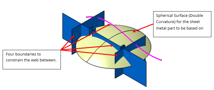


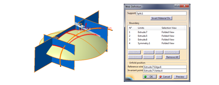
In the above, the Magenta curve is three dimensional and does not lie on the spherical surface nor any plane. There are also three surfaces that create a three sided boundary. Selecting the spherical surface as the Support and the other four geometries as Boundaries:

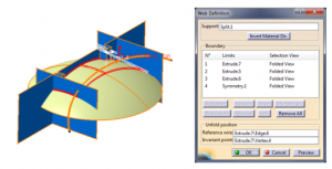
The resulting sheet metal part is as follows: 

For more information or to learn more about the Aerospace Sheet Metal Design workbench, please contact us.

